- Our PlaygroundOur PlaygroundDiscover Ax System's innovative solutions for maintaining the performance of your industry. Designed to meet the unique needs of each industry, our systems provide effective and efficient cleaning for a range of applications. Whether you're in power generation, oil and gas or any other sector, our tailor-made solutions ensure optimum performance and longevity of your equipment.
- Our SolutionsOur SolutionsDiscover AX System's range of products, designed to meet a variety of industrial cleaning needs. Our products fall into our main categories: Air Cooler and Air Condenser Cleaning, Industrial Misting, Custom Industrial Cleaning, and Industrial Machine Cleaning Services.
We offer specific solutions to meet your unique needs. For instance, we provide Filter Press Cleaners, Electromagnetic Filter Cleaners, and Rotary Filter Cleaners. - What we cleanWhat we cleanDiscover our expertise in high-pressure cleaning for a variety of industrial equipment! Our know-how enables us to work on air condensers, heat exchangers and many other installations. Thanks to our specialized approach, we guarantee optimum performance and enhanced durability for these vital pieces of equipment.
- Our Achievements
- About Us
- Contact

Component
The pump
The high-pressure pump provides the hydraulic energy necessary for the proper functioning of the AX Cleaner®. It is powered by electricity and uses fresh water. The pump is installed on the ground, beneath the heat exchanger, and supplies pressurized water to the cleaning head on the thermal exchanger via flexible hoses or stainless steel pipes, and powers the hydraulic motor of the pusher when it operates with water. It can be controlled from its control panel, or from the heat exchanger deck via a remote control (optional).
The model of the pump is primarily defined based on the power (flow and pressure) and the desired impact force (depending on the type of exchanger, the distance between the cleaning head and the fins, and the desired cleaning speed). Furthermore, many other parameters can adjust the configuration, such as the available eclectic supply (400V x 50Hz or 460V x 60Hz), ATEX zoning (IECEX, ATEX, NEC500…), and prevailing regional standards (IEC, NEMA…).The high-pressure pump provides the hydraulic energy necessary for the proper functioning of the AX Cleaner®. It is powered by electricity and uses fresh water. The pump is installed on the ground, beneath the heat exchanger, and supplies pressurized water to the cleaning head on the thermal exchanger via flexible hoses or stainless steel pipes, and powers the hydraulic motor of the pusher when it operates with water. It can be controlled from its control panel, or from the heat exchanger deck via a remote control (optional).
The model of the pump is primarily defined based on the power (flow and pressure) and the desired impact force (depending on the type of exchanger, the distance between the cleaning head and the fins, and the desired cleaning speed). Furthermore, many other parameters can adjust the configuration, such as the available eclectic supply (400V x 50Hz or 460V x 60Hz), ATEX zoning (IECEX, ATEX, NEC500…), and prevailing regional standards (IEC, NEMA…).
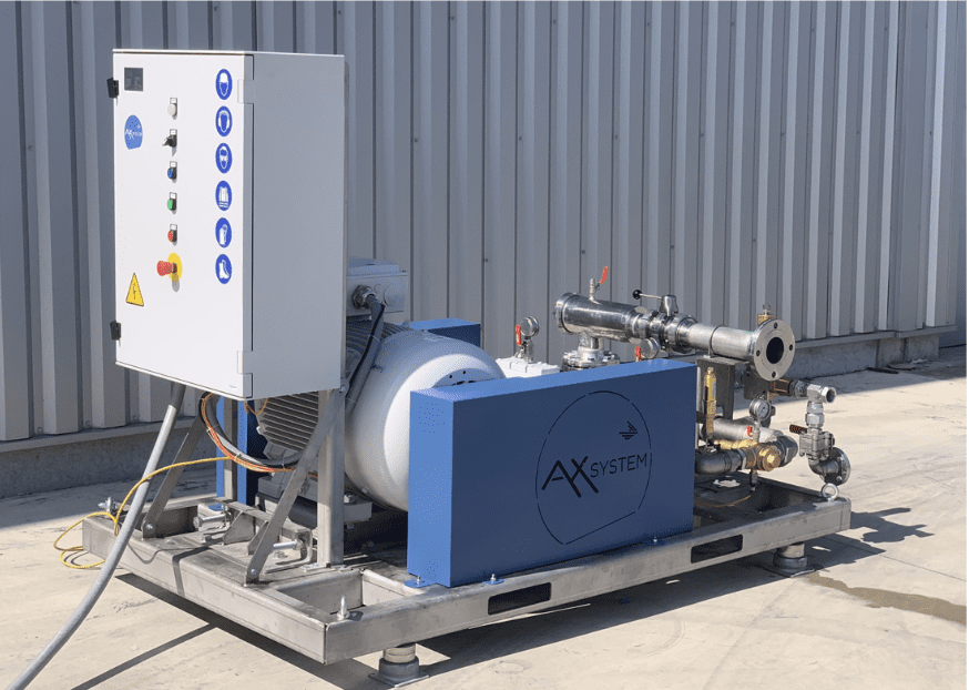
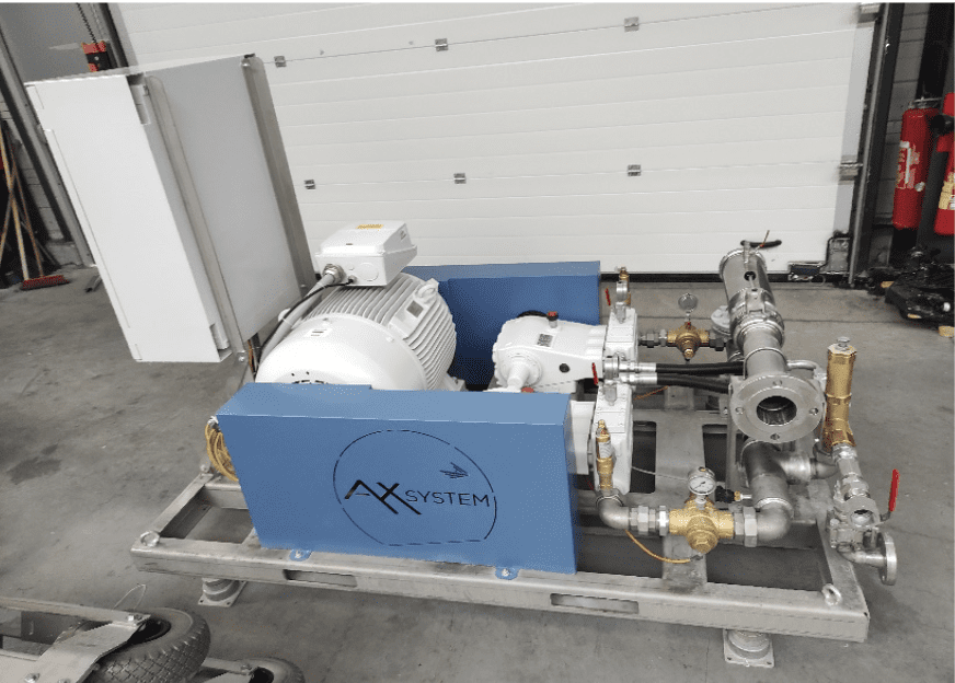
22kW 120L/Minute 90barg avec capotage insonorisation
22kW 150L/Minute 70barg ATEX Zone 2 T2
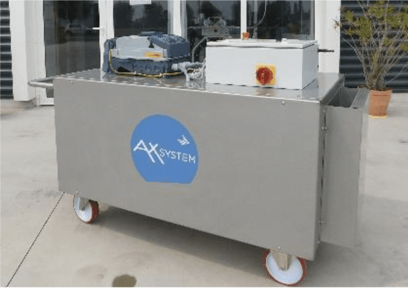
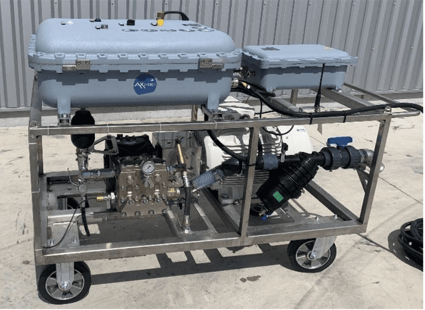
The hose pusher
Installed on the heat exchanger deck, at the foot of the bundles, this device ensures the vertical movement of the cleaning head by pushing and pulling the hose along a stainless steel sleeve up to the cleaning chassis. The drive between the motor and the hose is provided by a pair of adjustable-pressure polymer rollers, allowing the user to adjust the maximum force in case of an obstacle. Thanks to this innovative technology, the cleaning ladders lack any mechanical equipment necessary for moving the cleaning head (such as belts or chains), making them lighter, more reliable, and safer. This innovation is subject to several patent applications WO2021111081. We offer the hose pusher in 3 configurations:
- The portable hose pusher, installed at the bottom of the ladders. This is the simplest version to use since the hose pusher will move with the cleaning rigs during the cleaning operation without the operator needing to worry about it.
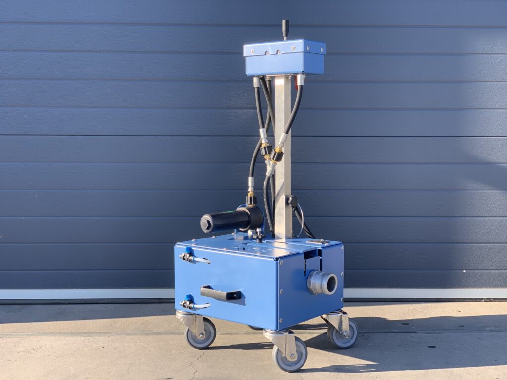
- The hose pusher on a wheeled cart. This configuration is recommended when it is not possible to fix the hose pusher at the bottom of the cleaning rigs. In this case, the hose pusher will be mobile, placed on the ground on wheels. The control panel is elevated on a pole to be at human height.
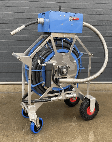
- The hose pusher with a reel. In the two previous configurations, the high-pressure hose runs on the ground during the cleaning operation. To secure the intervention, we also offer a hose pusher equipped with a reel to store the hose connecting the hose pusher to the cleaning head (up to 18 m of hose) and thus limit the risk of operator falls.
Two types of drives are available:
- Hydraulic water drive. No electrical power supply is then required at the level of the ACC deck. The hose pusher then uses part of the water flow provided by the pump (about 10 l/min) to operate, without any other connections required. This drive is widely favored for ATEX installations.
- Electric drive. The pusher must then be electrically powered (400-460V / 50-60 Hz).DISPOSITIF DE COMMANDE
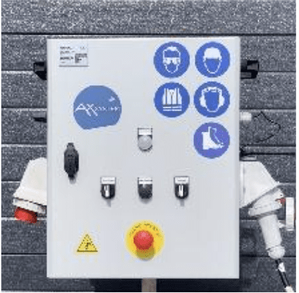
- CONTROL DEVICE
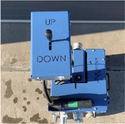
We offer two modes of control :
Manual control: in this case, the operator manually commands the direction of the nozzle carrier (up or down). At the end of the stroke, it is the operator who acts.
Automatic control: in this case, an end-of-stroke device allows the cleaning head to change direction automatically, without any action from the operator.
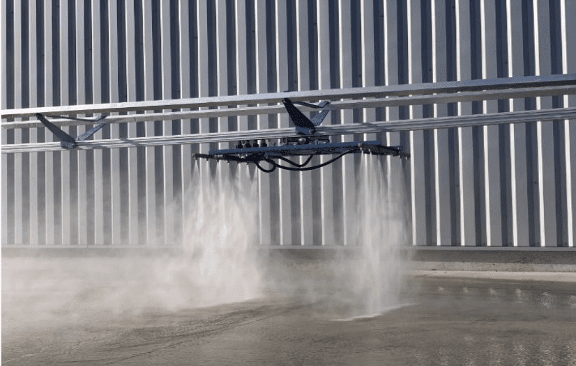
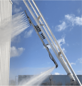
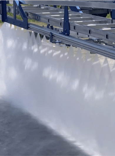
The cleaning head
The cleaning head sprays water under pressure onto the fins of the heat exchanger to ensure cleaning. Made of stainless steel, it slides on rails in two directions to cover the entire surface of the heat exchanger. It is equipped with nozzles along its entire length, projecting a flat conical jet that adapts to all finned tube technologies (flat aluminum tube, multi-row, etc.). The choice of the cleaning head should take into account various parameters, including the power of the pump used and the potential cleaning impact force provided by the pump, as well as the distance between the nozzles and the fins. The more powerful the pump with a strong impact force, the larger the cleaning head can be used, allowing for faster cleaning. Simply put, the larger the heat exchanger to be cleaned, the more advantageous it is to use a powerful pump combined with a large cleaning head.
Cleaning chassis
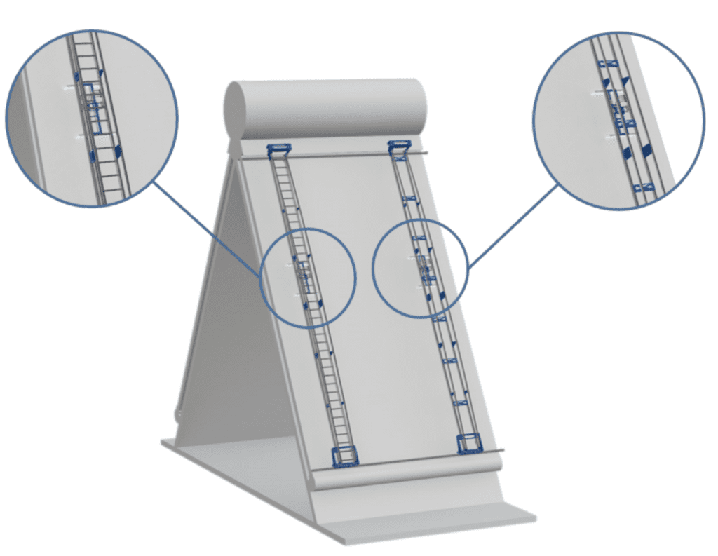
Cleaning rails guide the head and move it up and down (vertical axis). They slide horizontally to clean the entire length of the heat exchanger. There are five configurations:
- Single-rail cleaning rails: This is the simplest and lightest configuration, recommended for most heat exchangers, to be paired with single nozzle carriers.
- Access bi-rail cleaning rails: In addition to moving the cleaning head, these cleaning rails also serve as ladders, allowing an operator to climb onto the exchanger for another maintenance operation (for the cleaning itself, it is not necessary to climb onto the exchanger). These access bi-rail cleaning rails can optionally be equipped with an extension to even access the steam manifold. They are to be paired with bi cleaning heads.
- No-access bi-rail cleaning rails: These rails are recommended only if a bi cleaning head is available but there is no need to access the face of the heat exchanger. They are generally used in tandem with an access bi-rail equipped with an extension.
- Tire cleaning rails: This type of rail can be used on single-row thermal exchangers and does not require upper horizontal rails, as the rail rolls directly on the bundles. These rails are to be paired with a bi head.
Manual cleaning rails, which integrate their own nozzle carriers along their entire height. With this type of rail, there is no motorization (so no need for a pusher). The nozzle carrier is divided into 3 independent sections, partitioned by manual valves. The first third is cleaned, then the second, and finally the third, by manually moving the ladder along the length of the exchanger. Between each pass, the valves are switched to change sections. Manual rails require a more powerful motor pump and must be used by experienced operators to ensure cleaning is as effective as a semi-automatic or automatic system.
The design of our ladders has been the subject of extensive research to make them both lightweight and extremely reliable. They are protected by patent FR3124249.